
An Automotive Motor Tester helps technicians evaluate an electric motor’s electrical condition and performance. It may measure voltage, current, resistance, insulation, or winding balance. Some models also check vibration and operating speed. The exact tests depend on the motor and the tester.
During a test, leads or clamps connect the instrument to the motor or its circuit. The tester applies a controlled signal or reads live electrical values, then displays results for comparison. Howard W. Penrose, a motor-diagnostics expert, offers a useful principle in paraphrase: “Measurements need context.” A resistance reading, for example, can change with temperature, cable condition, or the test setup. Numbers alone do not tell the whole story.
This guide explains what an Automotive Motor Tester is, how its main tests work, and what its readings can reveal. It also considers the limits of these instruments. A tester is not a crystal ball. Incorrect connections, unsuitable test settings, or overlooked operating conditions can produce misleading results. Technicians should follow the manufacturer’s instructions and compare measurements with relevant specifications. Small details matter. A loose clamp or warm motor can affect a reading. Understanding those details helps turn a displayed value into a sound diagnostic decision.
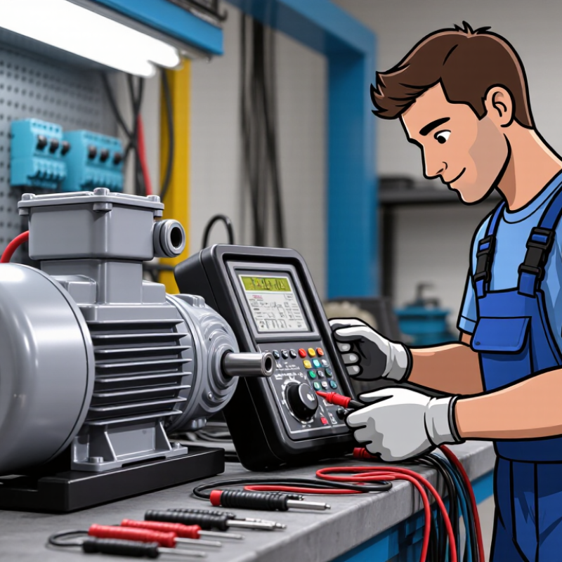
An automotive motor tester is a diagnostic tool for checking the electrical condition and performance of vehicle motors. It may be a dedicated analyzer or a set of test instruments, depending on the task. Technicians use it to investigate starter motors, cooling fans, blower motors, and window motors. Not every tester supports every test. That matters.
Common measurements include supply voltage, voltage drop, current draw, winding resistance, and continuity. A current clamp can show how much current a motor uses while operating. Excessive draw may point to mechanical drag or an internal fault, while low voltage at the motor can indicate a poor connection. Resistance readings help reveal an open winding, though a normal reading alone does not prove the motor is healthy.
Testing works best when readings are compared with vehicle service specifications and the motor’s operating conditions. A technician may inspect connectors, secure the vehicle, and check voltage during operation before removing a motor. Small details count. A loose probe can distort a reading, and testing an isolated motor may miss a wiring problem. Some results remain ambiguous; temperature, battery condition, and load can all affect them.
An automotive motor tester combines a controlled power source, measurement sensors, a load system, and analysis software. The power unit drives the motor, while voltage and current probes track electrical input. Speed and torque sensors show how output changes under load. Temperature and vibration sensors can reveal overheating or mechanical imbalance. Some benches also check winding resistance and insulation condition.
The International Energy Agency’s Global EV Outlook 2024 reports nearly 14 million electric car sales in 2023, about 18% of global car sales.
That growth makes repeatable motor testing increasingly useful for development and production checks. A dynamometer applies a measured load, letting technicians compare torque, speed, and efficiency across operating points. The software records results for review. No bench catches everything. A smooth test trace may still miss a fault that appears only after prolonged use, so test conditions matter.
Tips: Confirm sensor calibration and record motor temperature before each run. Keep test voltage, load, and ambient conditions consistent. Check safety interlocks before energizing the bench. Small setup differences can distort results; it is easy to overlook them.
A motor tester connects through the vehicle’s wiring harness, motor terminals, or battery cables, depending on the test. With the ignition off, inspect the connector and wiring for corrosion, loose pins, or damaged insulation. Then attach the tester’s leads to the specified terminals. A current clamp may fit around a cable without disconnecting it.
The exact connection depends on the motor and the tester. For a small fan motor, the test points may be its power and ground wires. For a starter, the procedure can involve high-current cables and requires equipment rated for that circuit. Follow the vehicle’s service information and the tester’s instructions. Never guess at a terminal. A poor connection can produce misleading readings, and a probe can damage a delicate wire seal. It is easy to rush this part.
Tips: Keep leads clear of moving parts. Check polarity before powering the circuit, and use insulated probes. If readings seem inconsistent, recheck the ground and connector fit before deciding the motor has failed.
An automotive motor tester turns electrical measurements into evidence about a motor’s condition. For a traction motor, technicians may record winding resistance, insulation resistance, voltage, and current; some systems also capture vibration or temperature. The test setup matters. Record the motor type, temperature, connections, and test conditions, so later readings can be compared fairly. Small details count.
Results are interpreted against service limits, phase balance, and earlier readings—not one number in isolation. A winding resistance mismatch can suggest a poor connection or damaged winding, while low insulation resistance may indicate moisture or deteriorating insulation. IEEE Std 43 provides guidance for insulation-resistance testing, but its limits must be applied with the motor’s design and operating conditions in mind. A clean reading can still mislead. Long leads, warm windings, or an incorrect test configuration can distort results.
Trends help reveal gradual deterioration before a motor fails under load. The IEA’s 2011 report, Energy Efficiency Policy Opportunities for Electric Motor-Driven Systems, estimated that motor-driven systems use about 45% of global electricity. That figure is not automotive-specific, but it shows why dependable motor performance matters. A useful test record includes raw readings, units, ambient conditions, instrument settings, and the technician’s interpretation. If a result seems unusual, repeat the measurement and check the setup before recommending repair.
An automotive motor tester applies controlled electrical or mechanical test conditions and records the motor’s response. The example below illustrates a bench test of a 12 V brushed DC motor; values are sample readings, not universal pass/fail specifications.
| Test Dimension | How the Result Is Collected | Illustrative Result | How to Interpret It |
|---|---|---|---|
| Test conditions | Record the motor type, rated voltage, ambient temperature, fixture setup, and test duration before testing. | 12 V brushed DC motor; 23 °C ambient; motor secured on a test bench. | Results are meaningful only when compared under consistent conditions and against the motor’s service data or manufacturer specification. |
| Supply voltage | A regulated power supply or tester measures voltage at the motor terminals while the motor is operating. | 12.0 V during the no-load run. | Compare terminal voltage with the required test voltage. A low reading can reduce speed and affect current readings. |
| Winding or terminal resistance | A low-resistance meter measures resistance across the motor terminals with power disconnected. For brushed motors, readings can vary with rotor position. | 0.18 Ω at the measured rotor position. | Unexpectedly high, unstable, or open-circuit readings may indicate poor connections, worn brushes, or a winding fault. Use an appropriate low-resistance measurement method for small values. |
| No-load current | A current sensor or tester records current after the motor reaches a steady speed with no external mechanical load. | 1.6 A at 12.0 V. | Compare with a known-good motor or specification. Excessive current may result from friction, bearing wear, misalignment, or electrical damage. |
| Rotational speed | A tachometer, optical sensor, or encoder measures shaft speed while the motor runs. | 4,800 rpm at no load. | Low or unstable speed can point to inadequate supply voltage, excessive friction, brush problems, or a motor fault. Compare at the same voltage and load. |
| Loaded current and torque | A dynamometer applies a controlled load; the tester records current and torque after readings stabilize. | 8.0 A and 0.12 N·m at the selected test point. | These readings show how the motor responds to load. Compare the torque-current relationship with the rated operating range; do not treat a single point as a universal limit. |
| Output power and efficiency | Mechanical output power is calculated from measured torque and speed. Efficiency is calculated by comparing mechanical output power with electrical input power. | About 50 W mechanical output at 4,000 rpm; about 52% efficiency if electrical input is 96 W. | For rotating equipment, output power is calculated as P = torque × angular speed. Efficiency depends on operating point and test conditions. |
| Insulation condition | When appropriate for the motor and its test procedure, an insulation tester measures resistance between isolated windings and the motor frame. | Record the measured value, test voltage, and test temperature; no universal sample value is assigned. | Interpret only against the motor’s specified procedure. Disconnect sensitive electronics and follow applicable safety guidance; an unsuitable test voltage can damage components. |
| Vibration and noise | An accelerometer records vibration, while a technician notes unusual noise during a steady-speed run. | Record vibration in mm/s RMS and document any clicking, grinding, or periodic noise. | Compare with the applicable service limit or a known-good baseline. Elevated vibration or abnormal noise may indicate imbalance, bearing wear, or mounting issues. |
| Temperature rise | A contact probe or infrared sensor tracks motor surface temperature during a defined operating period. | Record starting temperature, elapsed time, and final temperature; for example, 23 °C initially and 39 °C after 10 minutes. | Assess temperature rise in context of load, airflow, duration, and the motor’s specified limit. A rapid rise can indicate overload or excessive internal losses. |
| Overall assessment | The tester or technician reviews electrical, speed, load, vibration, and temperature results together. | Example outcome: readings are stable during the test; final status depends on comparison with the applicable specification. | A single measurement rarely confirms motor condition. Diagnose by checking test setup, connections, operating conditions, and related components before replacing the motor. |
Important: The figures above are illustrative, not acceptance limits. Automotive motors differ by design and application; use the correct service procedure and specified limits for the motor being tested.
Motor tests reveal different faults, so one reading rarely tells the whole story. The U.S. Department of Energy’s 2014 motor-system sourcebook estimates these systems use roughly two-thirds of U.S. manufacturing electricity. In a vehicle, testing a starter, fan motor, or traction motor can help separate electrical faults from mechanical drag.
A resistance test compares winding readings; a large imbalance may indicate a damaged winding or poor connection. An insulation-resistance test checks leakage between windings and the motor casing. A current or voltage-drop test can expose excessive load, weak supply, or high-resistance connections. For rotating motors, vibration and temperature readings may point to bearing wear or misalignment. Small clues matter. Readings need context: temperature, test setup, and manufacturer limits can change what counts as abnormal.