
Choosing the right Cable Lug is not a minor purchasing decision. It directly affects electrical safety, mechanical strength, heat control, and long-term reliability. A lug may look suitable on a shelf, yet fail under vibration, moisture, or repeated thermal cycling. The correct choice begins with the conductor material, cable size, insulation type, and installation environment.
Electrical educator Mike Holt offers a practical reminder: “Electricity is not forgiving.” That principle applies strongly to cable termination. Copper conductors usually require compatible copper lugs, while aluminum conductors need approved aluminum or bi-metallic designs. Mixing metals without proper protection can accelerate corrosion. The lug barrel must also match the conductor diameter. Too small, and strands may be damaged. Too large, and compression may remain weak.
Look closely at the installation details. Is the cable exposed to salt spray, underground moisture, engine vibration, or high current? A tinned Cable Lug can help in corrosive environments. A long palm may provide better contact on a busbar. The correct crimping die matters as much as the lug itself. A visually neat crimp is not automatically a reliable one.
Standards and manufacturer instructions should guide the final decision. Verify conductor class, stud-hole size, temperature rating, plating, and required torque. Field experience teaches an uncomfortable lesson: rushed terminations often appear acceptable during commissioning. They may fail months later. I would also question any selection based only on price. A cheaper lug can create costly heating, downtime, or rework. Careful inspection, documented torque, and approved tooling make the connection trustworthy.
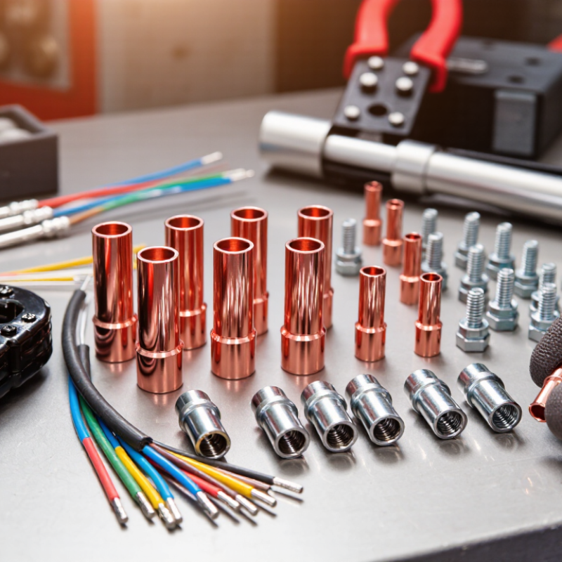
How to Choose the Right Cable Lug for Your Application?
A reliable cable lug starts with the conductor cross-section, not its outside diameter. IEC 60228:2023 defines nominal areas such as 1.5, 2.5, 4, 6, 10, and 16 mm². It also separates conductors into Classes 1, 2, 5, and 6. Class 1 is solid. Class 2 is stranded and less flexible. Classes 5 and 6 contain finer strands for flexible installations. The difference matters.
Choose a lug barrel that matches the conductor’s rated cross-section and class. A 25 mm² Class 5 cable may need a different lug design than a 25 mm² Class 2 cable. Fine strands can spread inside a rigid barrel. That may produce an uneven crimp. Poor compression can increase resistance and local heating. It may look acceptable. It is not always reliable.
The stud bore must also match the terminal bolt. A hole that is too small will not fit. An oversized bore can reduce contact area and permit movement. Check the bolt diameter, washer arrangement, and available clearance before crimping. IEC 61238-1-1:2019 evaluates electrical and mechanical performance for power cable connectors, including resistance and tensile behaviour. Use the specified die and compression sequence. Field inspections often find a polished crimp hiding damaged strands. That deserves a second look. Surface appearance alone is weak evidence.
| Conductor Cross-Section | Typical IEC 60228 Class Options | Conductor Construction | Nominal Lug Barrel Size | Barrel Selection Check | Typical Palm Mounting Hole | Compatible Bolt Size | Application Guidance |
|---|---|---|---|---|---|---|---|
| 1.5 mm² | Class 1Class 2Class 5 | Solid, stranded rigid, or flexible copper conductor | 1.5 mm² lug | Confirm the barrel accepts the actual conductor diameter and insulation strip length. | Ø4.3–Ø5.3 mm | M4 or M5 | Suitable for small control, instrumentation, and auxiliary power conductors. |
| 2.5 mm² | Class 1Class 2Class 5 | Solid, stranded rigid, or flexible copper conductor | 2.5 mm² lug | Flexible Class 5 conductors may require a flexible-conductor-compatible barrel. | Ø5.3–Ø6.4 mm | M5 or M6 | Common for branch circuits and control wiring. |
| 4 mm² | Class 1Class 2Class 5 | Solid, stranded rigid, or flexible copper conductor | 4 mm² lug | Do not select only by insulation outside diameter; verify the stripped conductor fits the barrel. | Ø5.3–Ø6.4 mm | M5 or M6 | Often used in compact distribution and equipment wiring. |
| 6 mm² | Class 1Class 2Class 5 | Solid, stranded rigid, or flexible copper conductor | 6 mm² lug | Use the lug’s specified crimp range and the correct die for the conductor and lug material. | Ø6.4–Ø8.4 mm | M6 or M8 | Common for feeder, battery, and equipment termination points. |
| 10 mm² | Class 1Class 2Class 5 | Solid, stranded rigid, or flexible copper conductor | 10 mm² lug | Check conductor strand formation, barrel length, and required crimp positions. | Ø6.4–Ø8.4 mm | M6 or M8 | Suitable for medium-current power and earthing connections. |
| 16 mm² | Class 2Class 5Class 6 | Stranded rigid, flexible, or very flexible conductor | 16 mm² lug | Class 5 and Class 6 conductors can have different strand layouts; verify the approved barrel range. | Ø8.4–Ø10.5 mm | M8 or M10 | Used for larger equipment feeds, bonding, and battery connections. |
| 25 mm² | Class 2Class 5Class 6 | Stranded rigid, flexible, or very flexible conductor | 25 mm² lug | Check whether the selected lug is rated for compact, sector-shaped, or circular conductors. | Ø8.4–Ø10.5 mm | M8 or M10 | Typical for distribution panels and medium-duty power circuits. |
| 35 mm² | Class 2Class 5Class 6 | Stranded rigid, flexible, or very flexible conductor | 35 mm² lug | Match both the conductor cross-section and the actual barrel internal diameter. | Ø10.5–Ø13.0 mm | M10 or M12 | Suitable for larger feeders, switchgear, and grounding conductors. |
| 50 mm² | Class 2Class 5Class 6 | Stranded rigid, flexible, or very flexible conductor | 50 mm² lug | For flexible conductors, use a barrel designed to prevent strand splaying during crimping. | Ø10.5–Ø13.0 mm | M10 or M12 | Common in industrial distribution and high-current equipment. |
| 70 mm² | Class 2Class 5Class 6 | Stranded rigid, flexible, or very flexible conductor | 70 mm² lug | Verify crimp-tool capacity, barrel wall thickness, and available installation clearance. | Ø13.0–Ø17.0 mm | M12 or M16 | Used for high-current feeders, switchboards, and power conversion equipment. |
| 95 mm² | Class 2Class 5Class 6 | Stranded rigid, flexible, or very flexible conductor | 95 mm² lug | Confirm the conductor’s actual outside diameter and the lug’s approved conductor range. | Ø13.0–Ø17.0 mm | M12 or M16 | Suitable for major distribution, transformer, and industrial power connections. |
| 120 mm² | Class 2Class 5Class 6 | Stranded rigid, flexible, or very flexible conductor | 120 mm² lug | Use a lug and crimp system qualified for the conductor class and installation environment. | Ø13.0–Ø17.0 mm | M12 or M16 | Typically used in high-capacity feeders and switchgear assemblies. |
| 150 mm² | Class 2Class 5Class 6 | Stranded rigid, flexible, or very flexible conductor | 150 mm² lug | Check whether the palm width and hole position fit the equipment terminal. | Ø17.0 mm | M16 | For high-current industrial, utility, and power distribution applications. |
| 185 mm² | Class 2Class 5Class 6 | Stranded rigid, flexible, or very flexible conductor | 185 mm² lug | Check the required number of crimps, tooling range, and minimum bending radius. | Ø17.0 mm | M16 | Used for large feeders, busbar connections, and high-power equipment. |
| 240 mm² | Class 2Class 5Class 6 | Stranded rigid, flexible, or very flexible conductor | 240 mm² lug | For parallel cables, verify phase spacing, palm orientation, and terminal loading. | Ø17.0 mm | M16 | Suitable for high-capacity switchgear, transformers, and industrial feeders. |
The mounting-hole sizes shown are common clearance-hole choices, not universal lug dimensions. Always verify the lug manufacturer’s dimensional drawing, crimping instructions, temperature rating, short-circuit rating, and compatibility with copper or aluminium conductors before installation.