
Discover Exciting Plastic Manufacturing Jobs at Allied Plastics

What Is a Pneumatic Punching Machine and How Does It Work?

A Pneumatic Punching Machine uses compressed air to create a controlled punching motion. It commonly cuts, pierces, embosses, or forms sheet materials. The machine may look simple, but its performance depends on pressure, tooling, material thickness, and timing.

Fluid-power educator Anthony Esposito explains the principle clearly: “Compressed air is not force until a system controls it.” Air begins in a compressor and passes through filters, regulators, and lubricators. A control valve then directs air into a pneumatic cylinder. The cylinder drives a punch toward a matching die. The punch enters the material, removes or reshapes a section, and retracts after the valve changes direction.

The process happens quickly. Sometimes, it is almost quiet. However, speed alone does not indicate quality. A clean hole requires proper clearance between the punch and die. Excessive clearance can leave rough edges. Insufficient clearance may increase wear or jam the tool. Operators must also match air pressure with the machine’s rated capacity. More pressure is not always better.

A practical inspection should include air leaks, loose fittings, worn seals, and damaged tooling. The workpiece should sit flat and remain stable during the stroke. Small mistakes matter. A slightly misaligned die can produce angled holes, cracked edges, or repeated failures.

This article examines what a Pneumatic Punching Machine is, how its air circuit operates, and why setup quality affects production results. The explanation is straightforward, but real machines are less tidy. Moisture, vibration, and inconsistent material can change the outcome.
What Is a Pneumatic Punching Machine and How Does It Work?

Definition and Core Purpose of a Pneumatic Punching Machine

A pneumatic punching machine is a production tool that uses compressed air to create holes, cutouts, or formed shapes in sheet material. Its core purpose is controlled, repeatable punching with less manual force. Air enters a cylinder and pushes a piston downward. The piston moves a punch through the workpiece and into a matching die.

The operator places material between the punch and die, then activates the machine through its control system. The die supports the sheet and helps define the finished shape. Proper alignment matters. Even a small offset can cause rough edges, distorted holes, or unnecessary tool wear. In practical workshops, operators often check air pressure, lubrication, and die condition before production begins.

Pneumatic punching machines suit light and medium-duty tasks involving materials such as metal sheets, plastic panels, and other workable surfaces. They can improve speed and consistency, especially when many identical holes are required. However, air pressure alone does not guarantee accurate results. Material thickness, punch clearance, machine rigidity, and operator setup all influence performance.

That assumption is incomplete.

From hands-on maintenance experience, neglected moisture in the air line can affect cylinder movement and reduce reliability. A machine may appear simple, but safe operation requires guarding, suitable tooling, and careful hand placement. Manufacturers provide technical limits, yet real production conditions still demand judgment. Testing a few pieces before full operation can reveal problems that specifications do not show.

Main Components and Their Functions

What Is a Pneumatic Punching Machine and How Does It Work?

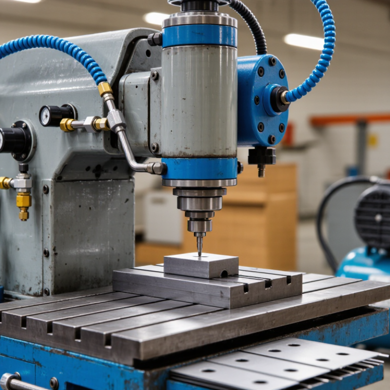
A pneumatic punching machine converts compressed air into controlled punching force. Its main components determine accuracy, speed, and operator safety. The air compressor supplies pressurized air through a filter and regulator. The filter removes moisture and particles, while the regulator controls working pressure. Stable pressure matters. Too much pressure can damage tooling.

A pneumatic cylinder changes air pressure into linear movement. When a control valve directs air into the cylinder, its piston pushes the punch downward. The punch enters the die and cuts or forms the material. A solenoid valve manages this air direction, often through a foot pedal or automatic controller. The machine frame supports the load, while guide posts help keep the punch aligned. Misalignment may create rough edges, unusual noise, or faster tool wear. In practical inspections, checking the die clearance often reveals problems before production suffers. It is easy to blame the cylinder.

Tips: Drain the air filter regularly. Check hoses for small leaks. Keep the punch and die clean. Operators should test one sample piece before running a full batch. A visible burr is a warning sign. Also, never treat a safety guard as optional. The correct pressure depends on material thickness, punch size, and tooling condition. A machine can appear powerful but still produce inconsistent results when air supply fluctuates. My view is simple: reliable punching begins with clean air, accurate alignment, and careful adjustment.

What Is a Pneumatic Punching Machine and How Does It Work? - Main Components and Their Functions

No. Main Component Primary Function How It Works in the Machine Typical Technical Information Maintenance or Safety Consideration
1 Compressed-Air Supply Provides the energy required to operate the punching actuator. An external compressor stores and delivers compressed air through piping to the machine. Common working pressure: approximately 0.5–0.8 MPa, depending on machine design. Use clean, dry air and size the compressor for both pressure and required air volume.
2 Air Filter and Water Separator Removes dust, liquid water, and some contaminants from the air stream. Incoming air passes through a filter element, while condensed moisture collects in a bowl for drainage. Typical filtration levels are selected according to the pneumatic system and manufacturer requirements. Drain accumulated water regularly and replace clogged filter elements.
3 Pressure Regulator Controls the air pressure supplied to the actuator. The regulator reduces upstream pressure to a stable set pressure, helping maintain consistent punching force. Punching force generally increases with cylinder bore and supplied pressure. Do not exceed the rated pressure of the cylinder, valve, hoses, or machine frame.
4 Lubricator Supplies a controlled amount of oil mist to compatible pneumatic components. A small quantity of lubricant is carried by the air into valves and cylinders when lubrication is required. Many modern components are designed for oil-free operation; follow the component instructions. Avoid adding oil to systems specified as non-lubricated, especially where product contamination is a concern.
5 Directional Control Valve Controls the direction of air entering and leaving the cylinder. A manually, mechanically, or electrically actuated valve sends air to extend or retract the cylinder rod. Common configurations include 3/2 and 5/2 valves, selected according to actuator type. Check valve response, air leakage, electrical connections, and exhaust ports.
6 Pneumatic Cylinder Converts compressed-air energy into linear mechanical motion. Air pressure acts on the piston, moving the rod downward to drive the punch and upward for the return stroke. Theoretical force is approximately F = P × A, where F is force, P is pressure, and A is piston area. Inspect rod alignment, seals, mounting bolts, and signs of air leakage.
7 Punch Tool Cuts, pierces, or forms the workpiece. The punch moves toward the material and enters or passes through the die opening to create the required shape. Tool material and geometry depend on the workpiece material, thickness, hole size, and production rate. Keep the cutting edge sharp and replace damaged tooling to prevent excessive force and poor-quality holes.
8 Die and Die Holder Supports the workpiece and provides the opening for the punch. The clearance between the punch and die allows the material to shear cleanly during the downward stroke. Required die clearance varies with material type, thickness, and tooling design. Align the punch and die accurately; incorrect clearance can cause burrs, tool wear, or breakage.
9 Guide Posts and Bushings Maintain alignment between the moving punch assembly and the die. Guiding elements limit lateral movement during the stroke and help maintain consistent tool clearance. Accuracy depends on guide straightness, fit, rigidity, and regular adjustment. Keep guide surfaces clean and lubricate only when permitted by the design.
10 Machine Frame Supports the cylinder, tooling, worktable, and other operating components. The rigid frame absorbs reaction forces and keeps the punching mechanism stable during operation. Frame capacity depends on allowable load, throat depth, working height, and structural rigidity. Check for cracks, loose fasteners, deformation, and secure anchoring to the floor or workbench.
11 Worktable and Material Stop Positions and supports the material during punching. The workpiece is placed on the table and located against a stop or fixture for repeatable hole placement. Table size and stop design determine the practical workpiece dimensions and positioning accuracy. Keep the surface flat, clean, and free from chips that could affect positioning.
12 Control Button or Foot Pedal Initiates the punching cycle. The operator activates the control, which sends a signal to the control valve or controller to start the stroke. Control mode may be single-cycle, maintained, or two-hand depending on the machine safety design. Position controls to prevent accidental activation and inspect cables, guards, and switches regularly.
13 Safety Guard and Interlock Reduces access to the punch area and helps prevent unintended operation. A guard blocks access, while an interlock can prevent the cycle from starting when the guard is open. Safety configuration must match the machine risk assessment and applicable workplace regulations. Never bypass guards or interlocks; verify their operation before production.
14 Silencer and Exhaust Port Releases exhaust air and helps reduce pneumatic noise. Air leaving the cylinder passes through the valve exhaust port and may be discharged through a muffler. Exhaust restriction can reduce cylinder speed and affect cycle consistency. Clean or replace blocked silencers and use hearing protection where noise levels require it.
15 Stroke and Speed Controls Adjusts the cylinder travel and movement speed for the punching process. Flow-control valves regulate air flow, while mechanical stops or sensors can limit the travel distance. Shorter strokes and controlled speeds can improve cycle time, tool life, and operating consistency. Set speed gradually; excessive impact speed may damage tooling, material, or the frame.
Basic Operating Sequence: The operator positions the workpiece, activates the control, and opens the directional valve. Compressed air drives the cylinder downward, moving the punch through the material and into the die. The valve then reverses or vents the air, allowing the cylinder to retract and complete the punching cycle.

How Compressed Air Creates the Punching Force

What Is a Pneumatic Punching Machine and How Does It Work?

A pneumatic punching machine converts compressed air into controlled mechanical force. Air enters a valve and pushes a piston inside a cylinder. The piston drives the punch toward the workpiece and die. When the valve changes position, exhaust air releases, and the piston returns. The cycle feels simple, but timing matters. A small delay can affect hole quality.

The basic force calculation is F = P × A. At 6 bar, a 50-millimeter cylinder bore can theoretically produce about 1,180 newtons. Real output is lower because of friction, pressure loss, seal wear, and imperfect alignment. The U.S. Department of Energy reports that compressed air may represent about 10% of industrial electricity use. Its compressed-air guidance also notes that leaks can waste 20% to 30% of compressor output. That waste directly reduces punching consistency.

Air preparation is therefore important. A filter removes particles, a regulator stabilizes pressure, and a lubricator may support compatible components. The Compressed Air and Gas Institute recommends controlling pressure drops and checking system leaks regularly. In practice, operators should inspect hoses, listen for hissing, and measure pressure near the cylinder. The calculation looks clean. Factory results rarely do. A worn die or flexible sheet can still produce rough edges, even when the gauge shows the correct pressure.

What Is a Pneumatic Punching Machine and How Does It Work?

How compressed air creates the punching force

The chart shows the theoretical pushing force produced by pneumatic cylinders with different bore diameters at 5 bar and 6 bar gauge pressure. Force is calculated as pressure × piston area, so a larger bore or higher air pressure produces more punching force. Actual machine output is slightly lower because of friction, seals, tooling, and mechanical losses.

The Step-by-Step Punching Process

A pneumatic punching machine uses compressed air to drive a punch through sheet material. It is common in workshops that need repeatable holes, slots, or shaped cuts. The machine includes an air cylinder, punch, die, worktable, regulator, and control pedal. Correct alignment matters more than speed.

The step-by-step process begins with a clean inspection. Check the air hose, guard, fasteners, and die opening before loading material. Set the regulator according to the material thickness and machine instructions. Excessive pressure can deform the sheet or damage the tooling. Place the sheet against the back gauge, then align the marked position beneath the punch.

Keep fingers outside the guarded area. Press the control pedal only when the sheet is stable. Compressed air pushes the cylinder downward, forcing the punch through the material and into the die. The slug falls through the die opening, while the cylinder returns after the stroke.

Release the pedal and inspect the hole edge for burrs, tearing, or distortion.

The first test is rarely perfect. Small alignment errors can create visibly uneven holes. I usually test one piece, measure the result, and adjust the gauge or pressure carefully. Watch for unusual noise, slow movement, or air leakage. Stop the machine when something feels wrong. A clean die and steady air supply often improve consistency more than faster operation.

Common Applications, Benefits, and Safety Considerations

A pneumatic punching machine uses compressed air to drive a punch through sheet material. The air cylinder delivers controlled force when the operator activates the control valve. A die supports the workpiece and shapes the hole or cut. Compared with manual punching, the machine can produce repeated results with less physical effort.

These machines are common in metal workshops, electrical cabinet production, appliance manufacturing, and light fabrication. They punch holes for fasteners, cable routes, ventilation openings, and assembly points. Operators can process aluminum, mild steel, plastics, and other suitable materials when the punch and die match the job. Production becomes faster and more consistent. Still, accuracy depends on alignment, material thickness, air pressure, and tool condition. A small setup error can create burrs, distorted holes, or wasted sheets.

Safety requires more than wearing gloves. Keep hands outside the die area, and use guards or two-hand controls where provided. Secure the workpiece before activating the machine. Loose material may shift suddenly. Inspect hoses, fittings, valves, and emergency stops before each shift. Release stored air before maintenance or tool changes. Eye protection helps prevent injury from chips and broken fragments. Hearing protection may also be useful in busy workshops. Operators need practical training, not only written instructions. In real workplaces, rushed production often weakens good procedures. That weakness deserves regular review.